 跳到内容
跳到内容 Control Valve Supplier
Your Trusted Electric/Pneumatic Control Valve Supplier
A control valve is a power-operated device essential for regulating the flow, pressure, temperature, or level of fluids, including gas, oil, water, and steam. It serves as the final control element in a process control loop, translating control signals into precise adjustments to maintain optimal system performance. Control valves are indispensable in industrial applications, offering unmatched accuracy and reliability for automation systems. With versatile designs and materials, they adapt to a wide range of operating conditions, making them the most widely used control element in industries today.
Self-operated Pressure Control Valve
Pneumatic Single-Seat Control Valve
Pneumatic Double-Seat Control Valve
Electric Single-Seat Control Valve
Electric Cage Control Valve
Electric Temperature Control Valve
REQUEST A QUOTE FOR MORE DETAILS
How to Choose the Right Pneumatic/Electric Control Valve for Your Project
What is a Control Valve?
Control valves are critical components in industrial systems used to regulate the flow, pressure, and temperature of fluids. These valves ensure the proper functioning of processes by maintaining system stability, enhancing energy efficiency, and preventing equipment damage. Without control valves, systems would be prone to pressure fluctuations, fluid wastage, or operational inefficiency, which could lead to costly downtimes.


What Are Control Valves Used For?
Control valves are used in various industries:
- Water Treatment: Managing water flow for optimal filtration and distribution, ensuring minimal energy consumption and waste.
- Chemical Processing: Regulating flow and pressure to control chemical reactions and maintain safety.
- Power Generation: Ensuring proper fuel and water flow, maintaining boiler pressure, and reducing energy consumption in power plants.
- HVAC Systems: Adjusting air and water flow for efficient heating, ventilation, and air conditioning.
- Oil & Gas Pipelines: Regulating pressure and ensuring safe transportation of oil and gas over long distances.
How Does a Control Valve Work?
Basic Functionality:
Control valves regulate fluid flow by adjusting the valve opening. This can be done manually or automatically, using either pneumatic or electric signals to control the movement of the valve. By changing the size of the valve opening, the flow rate is adjusted in real time to match the required system setpoints.
Key Control Mechanisms:
- Pneumatic Control: These valves operate using compressed air. The control signal is transmitted as pneumatic pressure that adjusts the valve’s position. Pneumatic control is ideal for high-flow or high-pressure applications.
- Electric Control: Electric control valves use electrical signals to control the valve’s actuator. They offer greater precision and can integrate easily with digital control systems for automated processes.
- Positioner: The positioner is a feedback mechanism that adjusts the valve’s position according to setpoint requirements, ensuring accurate control and minimizing the risk of error.

Key Components of a Control Valve
Control Valve Body
In the world of control valves, the internal design of the valve body significantly impacts how the valve operates, handles pressure, and controls flow. These designs determine the valve’s performance, and understanding them is critical when selecting the appropriate actuator.
Here’s a detailed breakdown of four common valve body designs that you’ll encounter in control valves:

Single-Seated Control Valve
Structure: The single-seated valve has a single plug that moves vertically in a seat, controlling the flow of fluid through the valve. The plug is pressed against a single seat when the valve is closed to prevent leakage.
Advantages:
- Simpler Design: With fewer parts, it’s easier to maintain and operate.
- Good for Moderate Pressure: Ideal for low- to moderate-pressure applications where precision control of flow is needed.
- Tight Shutoff: Provides a secure seal when closed, which is critical for systems that need reliable isolation.
Application: Water treatment, chemical processing, and applications with moderate flow and pressure.
Impact on Actuator Selection:
- This design typically pairs well with both electric and pneumatic actuators, depending on the precision and response speed needed for the application.

Double-Seated Control Valve
Structure: The double-seated valve features two plugs and seats, providing better stability and equalizing the forces acting on the valve plug. This design is used for higher flow and pressure applications.
Advantages:
- Higher Flow Capacity: With two seats, this design allows for a higher flow capacity than single-seated valves.
- Better Pressure Distribution: The two plugs help distribute pressure more evenly, which is particularly beneficial in high-pressure systems.
- More Stable Operation: The double-plug system helps prevent vibration and enhances valve stability.
Application: Used in higher-flow or high-pressure systems where increased stability is required, such as in oil & gas and power generation applications.
Impact on Actuator Selection:
- Pneumatic actuators are more commonly used with this design due to their high force output, especially in high-pressure systems. A positioner is often necessary to ensure precise control of both plugs.
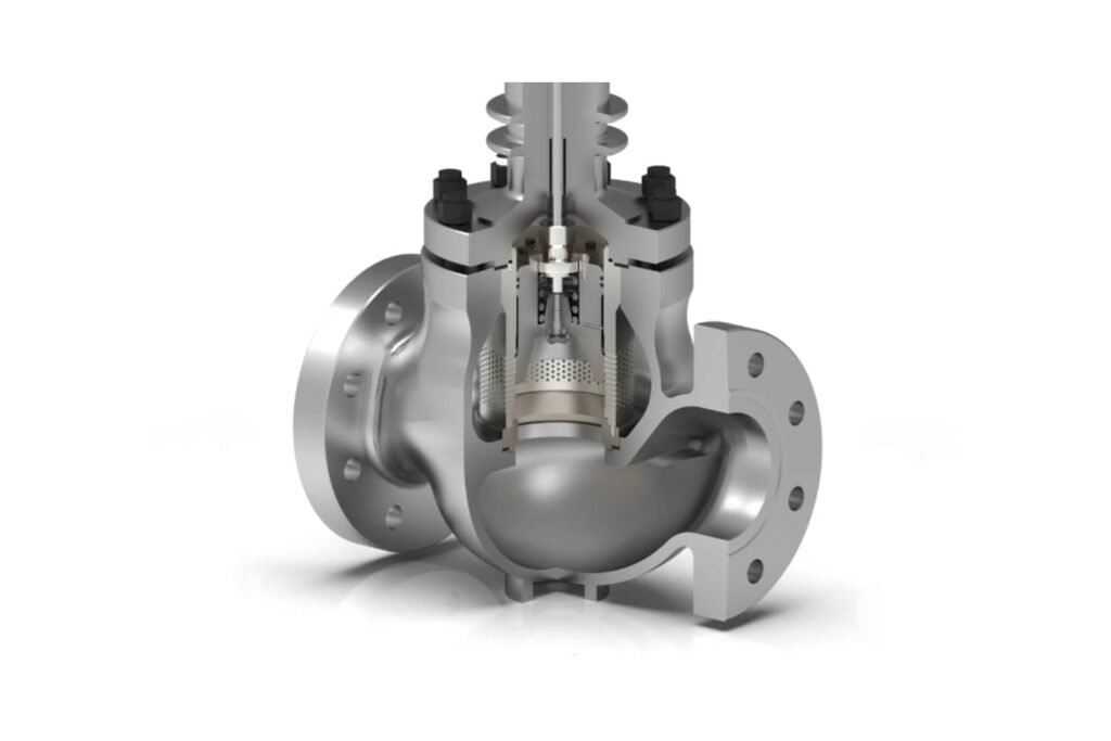
Cage-Guided Control Valve
Structure: A cage-guided valve uses a guide cage to control the movement of the valve plug. The plug moves within the cage, and this design is often used to regulate high-flow conditions and improve the accuracy of flow control.
Advantages:
- Improved Stability and Accuracy: The cage keeps the valve plug centered, preventing side-loading and ensuring smoother operation.
- Resistant to Flow Turbulence: The cage helps mitigate the effects of turbulence on valve performance.
- Higher Flow Capacity: Suitable for applications with high flow rates and pressure.
Application: Ideal for high-flow, high-pressure systems, such as in chemical processing, power generation, and water treatment plants.
Impact on Actuator Selection:
- Pneumatic actuators with a positioner are commonly paired with cage-guided valves. The positioner ensures precise control, while the pneumatic actuator provides the necessary force for large flow systems.

Multi-Stage Labyrinth Control Valve
Structure: The multi-stage labyrinth valve features a complex, multi-stage plug design that regulates flow through multiple stages or cavities. This design helps manage high-pressure differentials and ensures superior sealing, especially in extreme conditions.
Advantages:
- Handles High-Pressure Differentials: The multiple stages of the plug help equalize pressure, making it ideal for applications where large pressure drops occur.
- Prevents Cavitation and Flashing: By controlling the flow in stages, this design minimizes the risk of cavitation (the formation of vapor bubbles) and flashing (rapid phase change).
- Superior Sealing: The design ensures better sealing and greater operational integrity.
Application: Used in extreme conditions such as high-pressure gas systems, boiler feedwater, and cryogenic applications.
Impact on Actuator Selection:
- Pneumatic actuators with positioners are preferred due to the high forces required to operate the valve under high-pressure conditions. The positioner ensures precise movement across the multi-stage plug, enabling accurate flow control.
How Valve Design Affects Actuator Selection
| Valve Body | Best For | Recommended Actuator |
|---|---|---|
| Single-Seated Valve | Low to moderate flow, low-pressure applications | Pneumatic or Electric actuator (depending on need for precision) |
| Double-Seated Valve | High-flow, high-pressure applications, stable operation | Pneumatic actuator with positioner |
| Cage-Guided Valve | High-flow, precise control, stable operation | Pneumatic actuator with positioner |
| Multi-Stage Labyrinth Valve | High-pressure systems, preventing cavitation and flashing | Pneumatic actuator with positioner |
Choosing the right valve body design is just as crucial as selecting the correct actuator. Whether you need precise control in high-pressure systems or a stable and reliable flow for high-flow applications, understanding the characteristics of single-seated, double-seated, cage-guided, and multi-stage labyrinth valve designs will ensure that you achieve optimal performance and longevity from your valve systems.
Feel free to let me know if you need further modifications or additional details!
Control Valve Body (Valve Body Materials)
The valve body is the main structure of a control valve. It houses the internal components, connects to the pipeline, and is responsible for withstanding pressure, temperature, and corrosion. Material selection for the valve body is critical for ensuring the valve’s durability and performance.

| Component | Function | Material Options | Impact on Performance | Application Range (Temperature & Corrosion Resistance) |
|---|---|---|---|---|
| Valve Plug | Controls fluid flow passage | Stainless Steel, Inconel, Hastelloy, Monel, Duplex Steel | Ensures precise flow control, tight sealing, and durability. | Temperature: -200°C to 1000°C, Pressure: Up to 250 bar, Corrosion: Inconel and Hastelloy excel in harsh chemicals and high temperatures. |
| Valve Seat | Provides sealing surface to prevent leakage | Stellite, Tungsten Carbide, Ceramic, Chrome-plated Steel | Enhances sealing, particularly in high-pressure environments. | Temperature: -50°C to 1200°C, Pressure: Up to 200 bar, Corrosion: Stellite and ceramic materials provide excellent sealing in high temperatures and abrasives. |
| Seals & Gaskets | Prevents leakage from stem and bonnet | PTFE, Graphite, Fluoropolymers, Viton | High-performance sealing, ensuring zero leakage and reliable operation, especially in aggressive chemical and high-temperature environments. | Temperature: -200°C to 280°C, Pressure: Moderate to high, Corrosion: PTFE offers exceptional chemical resistance, Graphite for high temps, Viton for aggressive fluids. |
| Bonnet | Houses packing and protects the valve stem | Cast Steel, Stainless Steel, Alloy Steel | Ensures smooth operation and prevents leakage, reducing the risk of valve failure in high-pressure systems. | Temperature: -50°C to 500°C, Pressure: High, Corrosion: Stainless steel and alloy steel provide better corrosion resistance. |
| Valve Stem | Transfers force from the actuator to the valve plug | Stainless Steel, Alloy Steel | Ensures smooth operation and precise valve movement. | Temperature: -50°C to 800°C, Pressure: High, Corrosion: Stainless steel offers reliability; alloy steel is suitable for extreme high-pressure environments. |
| Packing | Seals the valve stem to prevent leakage | Graphite, PTFE, Elastomers (Viton, EPDM) | Provides sealing integrity, preventing leakage under pressure. | Temperature: -200°C to 280°C, Pressure: Moderate to high, Corrosion: PTFE offers excellent chemical resistance, Graphite for high temperatures. |
| Guide Ring | Guides the valve stem, ensuring smooth movement | Stainless Steel, Bronze, PTFE | Reduces wear and ensures smooth, reliable valve operation. | Temperature: -50°C to 300°C, Pressure: Low to moderate, Corrosion: Stainless steel and PTFE reduce wear and friction while providing long-lasting performance. |
| Seat Ring | Forms part of the sealing surface | Stainless Steel, Alloy Steel, Tungsten Carbide | Provides a strong seal and resists wear and corrosion. | Temperature: -50°C to 1000°C, Pressure: High, Corrosion: Tungsten carbide provides high wear resistance and corrosion protection. |
This table reflects the most important valve body components, along with their material choices and application suitability in terms of temperature, pressure, and corrosion resistance. It ensures that all relevant factors are considered when selecting materials for each component, helping customers make informed decisions about valve performance and durability in their specific operational conditions.
Feel free to let me know if you need further modifications or additional details!
Choose the Right Actuator for Your Control Valve
Struggling with Valve Control and System Performance?
In the world of industrial automation, achieving precise fluid flow control is critical to the success of your operations. Do you face challenges with slow response times, unreliable performance, or high maintenance costs in your valve systems?
Control valves play a crucial role in regulating flow, pressure, and temperature within systems, but without the right actuator, even the best valve designs can underperform. The actuator is what brings your valve to life, moving it to the correct position based on control signals. So, if you’re dealing with imprecise movements, inconsistent flow control, or increased maintenance, it’s time to consider how choosing the right actuator can address these issues.
How the Right Actuator Solves Your Problems
The correct actuator ensures your valve operates efficiently, safely, and consistently, leading to fewer issues and lower maintenance costs.
There are three primary types of actuators to choose from: electric, pneumatic, and self-operated. Each one offers distinct advantages for specific industrial needs. Let’s dive into how they can help you overcome common control valve challenges.

1. Electric Actuators
Power Source: Electric actuators rely on electrical power to generate rotary or linear motion. They are often equipped with motors (AC or DC), which convert electrical energy into mechanical motion.
Control Signal: Typically, an electric actuator receives a control signal in the form of a 4-20 mA current loop, which corresponds to the valve’s position. The actuator’s motor adjusts the valve accordingly based on this feedback.
Torque Generation: Electric actuators generate torque to rotate the valve stem or actuator shaft. The torque can be adjusted by controlling the motor speed or voltage supplied to the actuator.

Feedback Mechanism:
- Position Feedback: Electric actuators commonly include a position sensor (e.g., potentiometer or encoder) to provide real-time feedback on the valve’s position, ensuring that the valve is where it should be. This feedback allows for precise control and position adjustment.
Advanced Control Features:
- Electric actuators are ideal when integration with digital control systems is required, as they can interface with automated systems via fieldbus protocols like Modbus or Profibus.
- Some electric actuators have built-in controllers to fine-tune the valve position, and data logging capabilities to track valve performance over time.

2. Pneumatic Actuators
Power Source: Pneumatic actuators use compressed air to operate the valve mechanism. These actuators use cylindrical pistons to generate linear force, which translates into valve movement.
Mechanism of Action:
- The actuator consists of a piston inside a cylinder, with the air pressure applied to either side of the piston. The actuator’s position is controlled by adjusting the air supply to the piston.
- Spring-return pneumatic actuators (fail-safe type) use a spring mechanism to return the valve to its default position (usually closed) when air pressure is removed.
Integration with Positioners:
- Pneumatic actuators require positioners to convert the control signal (typically 3-15 psi or 4-20 mA) into the necessary air pressure to position the valve.
- A positioner receives the control signal from the control system, compares it to the current position of the valve (via feedback from the actuator), and adjusts the air pressure to move the actuator to the desired position.
- Pneumatic positioners are essential for precise control of the valve opening, ensuring that the valve operates smoothly within the required parameters.
Positioner Types:
- Single-acting positioners: Control a single direction of actuator travel (e.g., open or close), with the return direction being controlled by a spring.
- Double-acting positioners: Control both directions of actuator travel (open and close) without relying on a spring.
- Digital Positioners: Provide enhanced accuracy and can integrate with digital control systems to allow for more precise adjustments and diagnostics.
Advanced Control and Diagnostics:
- Some pneumatic positioners come with features like auto-calibration, self-diagnostics, and the ability to interface with advanced control systems such as DCS (Distributed Control Systems).
3. Self-Operated Actuators
Power Source: Self-operated actuators do not require an external power source (e.g., electricity or compressed air). Instead, they are powered by process variables such as system pressure or temperature.
Types of Self-Operated Actuators:
- Pressure-Actuated: Uses the system’s fluid pressure to operate the actuator. As the process fluid pressure changes, the actuator adjusts the valve position accordingly.
- Temperature-Actuated: Uses the system’s temperature to drive the actuator. These are common in applications where temperature fluctuations directly impact fluid flow, such as in steam systems.
Mechanism: The actuator contains a diaphragm or piston that is actuated by changes in system pressure or temperature. This motion moves the valve plug to adjust the flow.
Advantages:
- No External Power Required: They are self-sufficient and cost-effective in systems where an external power source (electric or pneumatic) is not available or necessary.
- Simple Design: Fewer components make self-operated actuators simpler and more reliable with fewer maintenance requirements.
Limitations:
- Limited Precision: They are less accurate and responsive than electrically or pneumatically actuated valves, making them less suitable for applications requiring fine control.
- Only Suitable for Certain Systems: They are best for systems where process conditions like pressure or temperature can be used to control the valve.
| Actuator Type | Power Source | Control Signal | Key Features | Suitability |
|---|---|---|---|---|
| Electric Actuator | Electricity | 4-20 mA, 0-10 VDC | High precision, digital integration, motor-driven | Best for precise flow control, integration with digital systems |
| Pneumatic Actuator | Compressed Air | 3-15 psi, 4-20 mA | High force, fast response time, needs a positioner for control | Ideal for rapid valve adjustments, large-scale, high-force needs |
| Self-Operated Actuator | Process Fluid Pressure | N/A | No external power, simple design | Best for small-scale systems with varying pressure or temperature |
The choice of actuator plays a crucial role in the performance of a control valve system. Electric actuators are ideal for applications requiring precision and integration with digital systems. Pneumatic actuators, when paired with positioners, provide reliable performance in high-force and fast-response applications. Self-operated actuators are a cost-effective solution for systems where external power is not necessary, but they come with limitations in terms of precision.
By understanding the technical differences between these actuators, engineers and operators can select the best actuator for their specific application, ensuring optimal performance, reliability, and efficiency in their control valve systems.
Frequently Asked Questions (FAQ) – Buying Control Valves
1. What are control valves used for?
Control valves regulate the flow, pressure, and temperature of liquids, gases, or steam in industrial processes. They are widely used in industries such as water treatment, chemical processing, oil & gas, and power generation to maintain system stability and efficiency.
2. What are the main types of control valves?
BYZER offers a range of control valves, each designed for specific applications:
Self-Operated Pressure Control Valve – Adjusts pressure without external power, ideal for steady-state flow applications.
Pneumatic Single-Seat Control Valve – Provides precise regulation with a single-seat design, minimizing leakage.
Pneumatic Double-Seat Control Valve – Designed for larger flow rates and balanced pressure control.
Electric Single-Seat Control Valve – Uses an electric actuator for precise automated flow control.
Electric Cage Control Valve – Incorporates a cage structure to handle high-pressure differentials and reduce noise.
Electric Temperature Control Valve – Integrates temperature sensors for automated temperature regulation.
If you require other materials, special configurations, or custom solutions, we offer fully customizable control valves to meet specific industrial needs. Contact us for tailored solutions!
3. How do I choose between pneumatic, electric, and self-operated control valves?
Pneumatic Control Valves: Suitable for applications requiring fast response, reliability in hazardous environments, and high force output. Best for process industries such as chemicals, water treatment, and oil & gas.
Electric Control Valves: Ideal for precise control, remote operation, and automation. Commonly used in HVAC, food processing, and power generation.
Self-Operated Control Valves: Best for applications requiring automatic pressure regulation without external power. These valves use the process fluid’s pressure to adjust flow, making them highly reliable for steady-state systems in industries like steam control, gas regulation, and water distribution.
4. What materials are available for control valves, and how do I choose?
The material selection depends on the fluid type, temperature, pressure, and corrosion resistance:
Cast Steel (WCB, WC6, WC9) – Suitable for oil, gas, and high-temperature applications.
Cast Iron/Ductile Iron – Cost-effective option for water and HVAC applications.
Stainless Steel – Excellent for corrosive environments, available in different grades:
SS304 – Good corrosion resistance for general industrial applications.
SS316 – Enhanced resistance to chemicals, acids, and seawater.
SS316L – Low-carbon version for better weldability in sanitary applications.
Duplex Stainless Steel – Higher strength and corrosion resistance for aggressive chemicals.
Bronze or Brass – Commonly used in potable water and lower-pressure applications.
PTFE-lined or Rubber-lined Valves – Ideal for highly corrosive media and chemical processing.
If your application requires special materials or coatings, we provide customized solutions to ensure durability and performance. Contact us for expert recommendations!
5. What factors should I consider when sizing a control valve?
Proper sizing is essential for efficiency and longevity. Consider:
Flow rate (Cv value) – Determines the valve’s capacity.
Operating pressure and temperature – Ensures compatibility with process conditions.
Inlet and outlet pressure differentials – Affects valve performance.
Flow characteristics (linear, equal percentage, quick opening) – Helps match process needs.
6. What are the different flow characteristics of control valves?
Linear – Flow changes proportionally with valve position, useful for pressure control.
Equal Percentage – Small valve openings create low flow changes, while larger openings result in exponential flow increases, suitable for temperature and flow control.
Quick Opening – Rapid flow increase at small openings, ideal for safety applications.
7. What types of actuators are available for control valves?
Pneumatic Actuators – Fast and reliable, suitable for continuous process adjustments.
Electric Actuators – Precise and ideal for remote operation and automation.
Self-Operated Actuators – Utilize process pressure to adjust flow automatically, eliminating the need for external power sources.
8. What are the common end connections for control valves?
Flanged – Secure and widely used in industrial applications. Common standards include:
ANSI/ASME B16.5 (American Standard)
JIS B2220 (Japanese Standard)
DIN EN 1092-1 (European Standard)
GB/T 9112-2010 (Chinese Standard)
Threaded – Suitable for smaller pipelines and low-pressure systems. Common types:
NPT (National Pipe Thread, U.S. Standard)
BSP (British Standard Pipe, includes BSPP & BSPT)
G Thread (ISO Parallel Thread)
Welded – Provides a permanent, leak-proof connection for high-pressure applications. Standards include:
ANSI/ASME B16.25 (Butt-Weld Ends)
DIN 3239 (European Welded Standard)
GB/T 12224-2015 (Chinese Welded Standard)
Tri-Clamp – Commonly used in food, beverage, and pharmaceutical industries. Standards include:
SMS 1145 (Swedish Standard for Dairy and Food Processing)
3A Sanitary Standard (U.S. Sanitary Standard)
DIN 32676 (European Clamp Connection Standard)
ISO 2852 (International Clamp Standard)
DS/BS Standards (Widely used in sanitary piping systems)
Selecting the appropriate end connection ensures compatibility and reliability in your piping system. For specialized requirements, contact us for expert guidance!
9. What industry standards should control valves comply with?
ANSI/ASME B16.34 – Governs pressure-temperature ratings.
API 598 – Standard for valve testing and leakage control.
ISO 9001 – Quality management certification.
ATEX & SIL Compliance – Required for hazardous environments.
10. How can I reduce maintenance and extend the lifespan of a control valve?
Choose high-quality materials to prevent wear and corrosion.
Select a modular design with replaceable trim for easy servicing.
Regular inspections and lubrication improve performance.
Ensure spare parts availability to minimize downtime.
11. How do I balance cost and performance when selecting a control valve?
While cost is a key factor, investing in a high-quality valve ensures:
Lower maintenance costs over time.
Greater reliability and process efficiency.
Reduced downtime and increased operational stability.
12. Where can I get expert advice on selecting the right control valve?
At BYZER Valve, we provide expert guidance and customizable control valve solutions tailored to industrial applications.
Contact us today for technical assistance and product recommendations!
Let's Started Today!
If you’re seeking the ideal valve solution for your industrial projects, we’re here to support you.
Tell us your requirements, and our team will provide the guidance and information you need to make the best decision for your operations.
Reach out now to enhance your systems with our reliable and efficient valve technologies.
Support
info@byzervalve.com
Ask For Quote Now!
Reply Within 24 Hours
Your email is confidential and safe with us. Our team guarantees your privacy.
